PUPS 2 | Exact Constraint Analysis
Introduction
This simple planar exact constraint (EC) system lets users explore sensitivities of fixturing a planar object. The wooden pin design, shown below, with multiple peg placements allows the user to experiment with different arrangements of constraints – both exact and in-exact.
“An unconstrained rigid object has six degrees of freedom usually identified as three translations and three rotations. A non-rigid object may have one or more degrees of flexibility that act as additional degrees of freedom.” [1] Two particularly helpful references in understanding exact constraint and the relatively positioning of the pins and preload force is Design Principles for Precision Mechanisms by Herman Soemers and related lecture notes from Professor Dannis Brouwer.

Assignment
-
Design a simple planar exact constraint system to let a user explore sensitivities of fixturing a planar object. Allow the user to experiment with different arrangements of constraints.
-
Model the system to predict the forces on the constraining points as a function of where the forces are applied to the object.
-
Create a spreadsheet or MATLAB script to embody your model and produce output helpful to you as a designer.
-
Modify your design as you see fit by the results of the analysis, and build it!
-
Explore the sensitivity (both by feel and using your spreadsheet or script) of where should the constraints be located.
I began this exploration by understanding the basic physics in my notebook. An exact constraint model needs to account for the geometry of object being constrained, the force body analysis of forces in the x and y directions, moments on the object, the location and angle of preload applied, and the friction between the object and the pins.
To better understand the interaction of the coupling parts, I built a Matlab model using linear algebra to solve for the forces at each of the pins. The model accounts for gravity, but does not take into account the fictional interaction between pins and object.
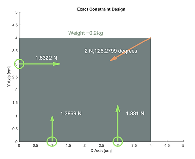
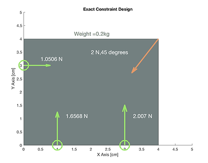
Shown below is the graphical output of my model in several configurations. The green circles and arrows represent the pin locations and the orange arrow represents the preload applied. All arrows are scaled by the force represented.
Constrained and stable, forces unbalanced between pins.

Constrained and stable and good balance of forces.
Constrained and stable and good balance of forces.
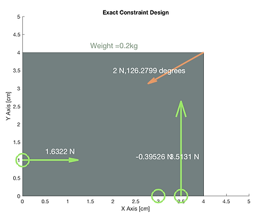
Unstable and not constrained.
Fabrication
I build a SolidWorks model of the pin configuration seen in the model image above. I sized the holes to 0.25 inches and found wooden dowel pins slightly undersized to press fit. I scavenged a piece of plywood from the Hobby shop, exported my design to MasterCam and used the ShopBot router to cut the holes. The final finish was underwhelming as the plywood veneer left jagged edges around the holes even though I had chosen a sharp bit. Even so, the coupling makes a nice desk decoration to hold my business cards.
Peer Review
During fabrication I noticed that the holes were significantly variable in size, in some the dowel pins needed force to press in, for other holes they slid in, and in others they wouldn't fit in at all. This was surprising as I had used the same bit at the same feeds and speeds for the entire part. After talking it over with Maha, we surmised that the variability could be due to knots in the wood which would cause changes in the density of the wood and glue between the layers which might chip unevenly compared to the wood.
[1] Hale, Layton C. “Principles and techniques for designing precision machines.” MIT PhD Thesis, 1999.